Transmission electron microscopy
Tecnai Spirit
Acquired 2014
How-tos
-
Setting up Intensity (INT, C2) properly for your image
Description
Handling the intensity button is probably the key factor in creating good images. Too much intensity (over-illumination) and too low intensity (noisy images) must be avoided.
Difficulty
Easy. Must be performed by all users
Protocol
This howto displays all steps from over to under-illumination, accompagnied by examples and typical artefacts you will encounter at each step.
The C2 setting is relative to your microscope setting and never an absolute value. The higher the magnification, the closer C2 will get to the 37/38 cross-over. Furthermore, also C1 (spot size), sample and apertures will influence this value. Therefore, it makes no sense to write down C2 values. The C2 values in this HowTo should be interpreted as relative. Better is to interpret the image and react on it.
Starting point: over-illumination with beam edges
Observation
- Beam edges visible (white arrows). Note: Beam edges are curved, if the black edge is straight then it is not the beam edge but the outside edge of the objective aperture (see below: Align a severely misaligned objective aperture).
- The indication bar on the histogram touches the red on the right
- C2 Lens is close to 38%
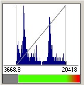
C2: 39.65% 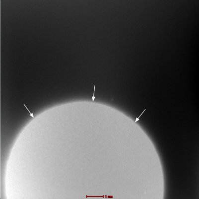
Action: center the beam edges
Warning: you are potentially damaging the detector. Act now and quickly!!
- Center the beam with the trackball (left panel)
- Increase C2 until the edges touch the side of the image.
Result
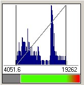
C2: 41.28% 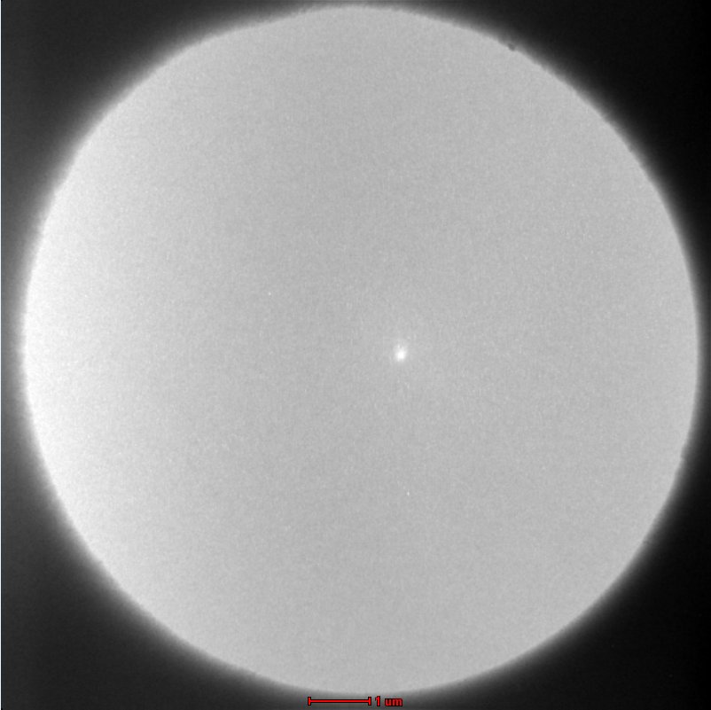
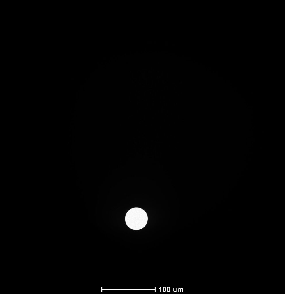
Note the small white dot near the center. This is the result of letting a cross-over beam too long (several minutes) on the detector. It cannot be repaired but is not visible in the images.
Step 1: Over-illumination
Observation
- While increasing C2 the beam edges spread and are no longer visible on the images.
- Continue until no black beam edges are visible anymore
- The image is replaced by a dark gray, static image with a white dot near the center.
- The range indicator of the histogram is short and firmly in the red
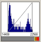
C2: 39.65% 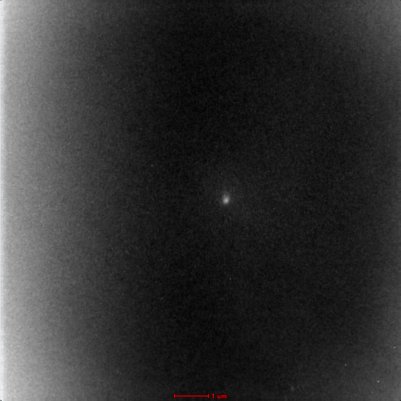
Action
Warning: you are still putting a lot of electrons on the detector. Proceed swiftly.
- Further increase C2
Step 2: dynamic pixels
Observation
- While further increasing C2 the dark gray image loosens at the edges: some pixels become dynamic: not longer static and prone to noise.
- There is still a part of the image that is dark gray and static, usually in the central part. If you are lucky, you may see already part of your samples on the left an right side of the image.
- The range indicator of the histogram is getting longer but still touching the red part of the range.
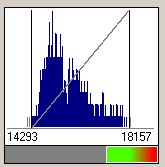
C2: 44.61% 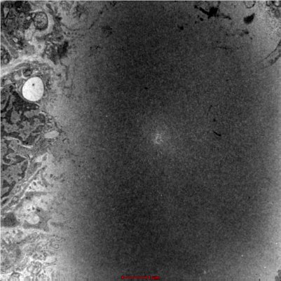
Action
- Further increase C2
Step 3: Perfect illumination
Observation
- While increasing C2 the dark gray static patch in the center disappears
- All pixels in the image are dynamic: i.e. prone to noise.
- The range indicator of the histogram is long and green
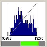
C2: 39.65% 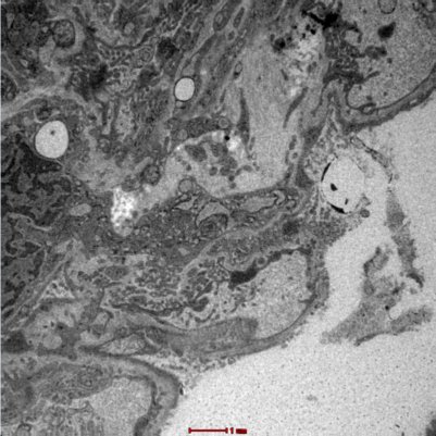
Action
This is the moment to record your image
- Record your image
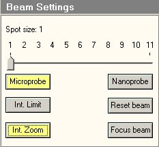
- You may want to switch on the Intensity zoom (Beam > Beam Settings > Int Zoom), which will take care of C2 as you change magnification.
Step 4: noisy illumination
Observation
- While increasing C2 increasingly more noise gets into the image
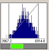
- The range indicator of the histogram is shortening, moving to the left but still green
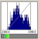
C2: 39.65% 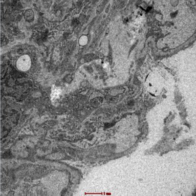
Action
This is still an acceptable setting for images, and may be your best setting at higher magnifications depending on the contrast in your sample. As a example, below is a recording of a 70 nm thick biological section at 300k X, with range indicator
C2: 38.57%, Mag: 300kX 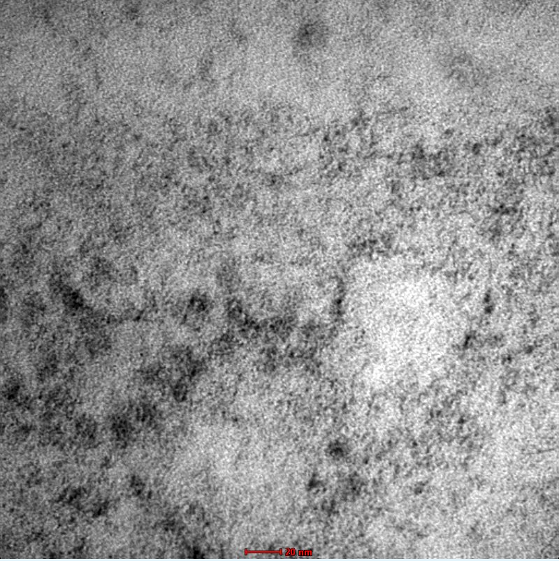
Step 5: under-illumination
Observation
- While increasing C2 the noise becomes very apparent
- From the center downwards, the image seem to ‘sag’ out
- The range indicator of the histogram is short, close to the left and blue
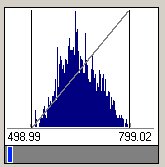
C2: 61.08% 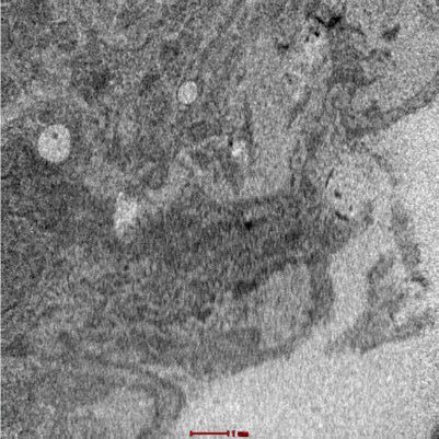
Action
- decrease C2 until the range indicator moves to the right and turns green
-
Copy data to a UniFr server (Common, Bigdata). AMI only
Description
Avoid the use of USB sticks and external HD (they are usually a liability as they can import virusses). Better, faster and more reliable is to copy your data directly to the UniFr server (Personal Exchange folder, Group folder, Bigdata, personal folder)
Remedy
Map the required network drive
Time requirement
About 1 minute
Difficulty
Easy
Note
This help is only valid for AMI users
Protocol
Map the required network
- Open the file manager on the support PC:
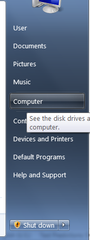
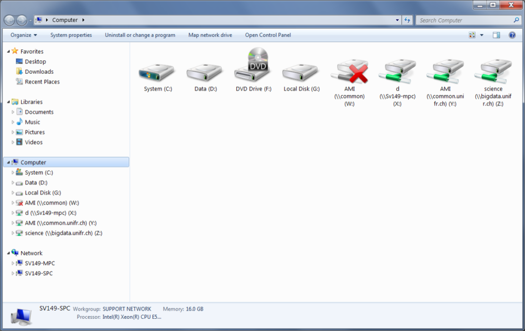
- Right click Computer & choose “Map network drive” or just click Map network drive in the title bar.
- Choose the correct server
Common \\common.unifr.ch\AMI Bigdata \\bigdata.unifr.ch\Science\AMI\Data “Common” will give you access to the groups folder and to the personal exchange - Check “connect using different credentials
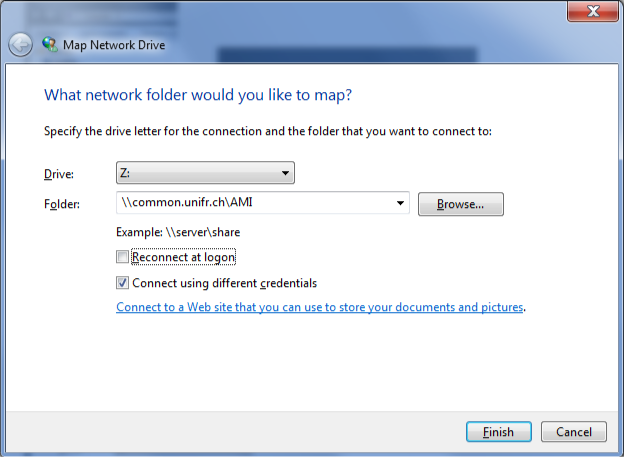
- Next will be your credentials. Precede your user name with unifr\ in order to get unifr\<your UniFr user name>
- Do not check “remember my credentials”
- Click OK
-
How to retrieve liquid nitrogen when the 25L dewar is empty
Notice: You must be trained in the handling of LN2. If you are not, please contact your local security officer.
- Use the 25L dewar at the entrance of A017 to fill the 1L Dewars of the TEM.
- If that 25L dewar is empty, refill it at the LN2 tank on the other side of the building.
- Roll the 25L dewar to Building C and put it in the elevator (after the lobby, left). Do not enter the elevator with the LN2 tank! Batch on the sensor in the elevator to send the elevator to -1.
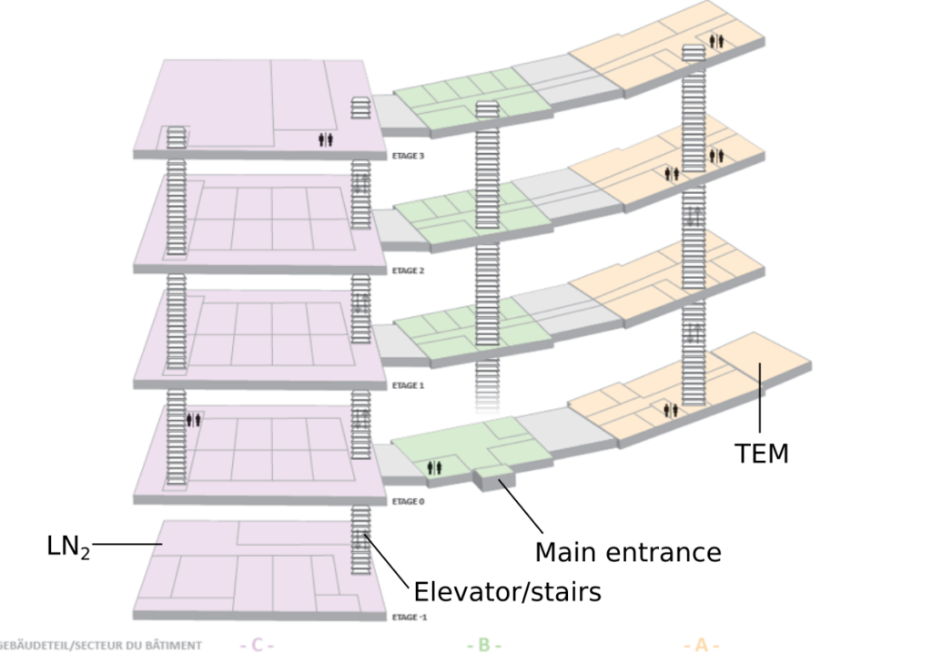
- Take the stairs to -1 on the right side after the lobby.
- Pick up the Dewar from the elevator and roll it to the far end of the building. Here, you will find a table with a laptop and a large cupboard. Login onto the laptop (the credentials are available on the table).
- Use the following settings to take LN2 for the TEM (and TEM only!):
Taker TEM user For TEM user Volume 25L - Sign on the screen
- Write the same details on the sheet that you will find on the table.
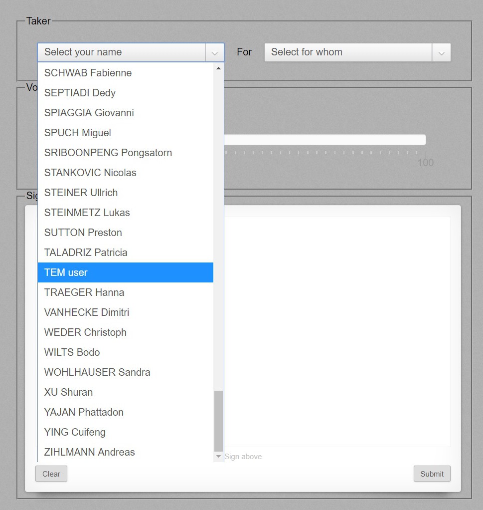
- In the cupboard, you will find all the protective tools required. Also you will find a key. Take this key and roll the dewar outside to the large LN2 tank.
- Open the Door with the key, put the LN2 finger in the dewar and open valve 32A. Fill the dewar until full (~5 minutes).
- close the valve, close the door and leave the protective gear and key where you found them. Roll the dewar back to the TEM room. Do not ride in the elevator with a full tank of LN2. Put the 25L dewar in the elevator and send it to 0. You take the stairs.
-
Load the latest master alignments
Description
After you started the beam, it is visible on the fluorescent screen but is is dimmer as it used to be.
Remedy
Load the latest master alignments
Time requirement
About 30 seconds
Difficulty
Easy
Protocol
Find the Alginment Tab
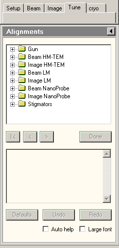
- Open the Microscopy user interface and find the Tune tab in the workset tabs (top left)
- In the Tune tab, locate the alignments window
Find the master alignment files
- Click the flapout (triangle in the Alignments title bar, on the right and select the tab “File”.
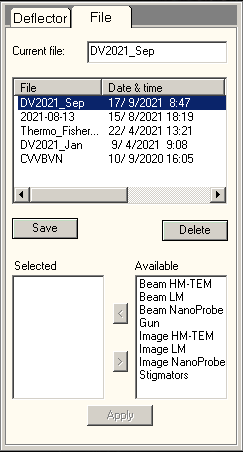
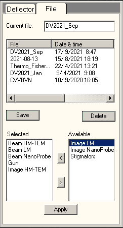
- Click “Date & Time” to find the most recent entry. Select that most recent file.
- Then, double click all available alignments in the “Available” list until all show up in the “Selected” list.
- Click Apply.
-
Selected area electron diffraction algorithm
Description
How to perform diffraction on your sample with correct focus and parallel beam
Time requirement
About 1 hour
Difficulty
High
Protocol
Spot size
All the steps below assume you do not change the spot size. Define a spot size at the start of your experiment and stick to it. If you are unsure: load your sample, do a quick and dirty diffraction pattern and retrieve the spot size where the pattern looks ok in terms of signal to noise.
Cross grating
Load a Au cross grating grid.
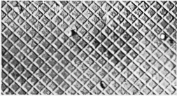
- Perform eucentric height (take care to do this accurately)
- Run the eucentric focus
- Find a cluster of Au, go into diffraction. Remove the objective aperture.
- Choose a camera length where you see the diffraction rings filling the fluorescent screen (2 rings)
- Use the intensity button to focus the central, unscattered beam.
- Use the focus knob to focus the scattered rings.
- Do to the longest camera length. D=8.9 m
- Use the intensity button to focus the central, unscattered beam again. Write down the value of C2 (or do not touch intensity anymore).
Load your sample
Load your grid with the sample.
- Perform eucentric height (take care to do this accurately, again!)
- Run the eucentric focus.
- Do not touch intensity (or set it to the value you noted down).
- Go into diffraction.
- Choose an appropriate camera length. Insert the Beam stopper and use the MF buttons to align the pattern so the central beam is blocked.
- Use the focus knob to focus the diffraction pattern. Do not touch the intensity button.
- Do not change the spot size (C1).
- Do not lift the fluorescent screen!
Troubleshooting
-
Software freezes at startup / reboot the microscope PC
Description
The software of the microscope user interface freezes at startup. Visible is the splash screen, even after more than 1 minute waiting.
Remedy
Restart of the microscope PC
Time requirement
About 10 minutes
Difficulty
Easy
Protocol
PC restart
- Close all software on the microscope PC (the one on the left, running the microscope user interface and the camera software).
- In Windows, find at the bottom left the START button. Click it and choose SHUT DOWN. Then choose RESTART.
- Let the PC restart, then login using your TEM credentials
- You can now stay and monitor the rest of the startup, or you do something else and come back in 5-10 minutes: the startup runs automatically.
Server restart
- DO NOT START THE MICROSCOPE USER INTERFACE. Find in the Windows notification area at the bottom right. A microscope server icon will appear
- You need not to do anything. Just wait and follow the server setup if you want:
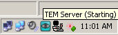
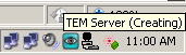
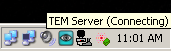
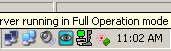
Hoover the mouse over the icon to see the messages.
When the microscope server icon in the notification area has turned “green”, you can start the microscope user interface
-
Left or right panel not reacting / not working
Description
One (or both) of the control panels is not reactive anymore.
Remedy
Restart of the microscope PC
Time requirement
About 10 minutes
Difficulty
Easy
Protocol
See above: Software freezes at startup
-
Joystick: stage moves in X but not in Y direction
Description
The stage moves in the X direction (up/down), but not or hardly in the Y direction (left/right), although you hear the piezo motors being active
Remedy
Holder not fully inserted
Time requirement
Seconds
Difficulty
Easy
Protocol
- Close the column valves (to avoid air leaks)
- Check the holder: it is not fully inserted.
- wiggle gently until the groove on the far side falls into the goniometer pin (about 2-3 mm)
- Re-open the column valves.
-
Pump does not start when inserting the holder
Description
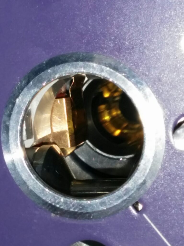
After insertion of the holder, a mechanical sensor signals the pump to start automatically. This mechanical sensor is extremely sensitive and can sometimes get stuck after removing the holder. In seldom cases, this causes the sensor not to send the signal to the pumps.
Remedy
Unstuck the brass plate of the sensors inside the goniometer
Time requirement
Seconds
Difficulty
High
Protocol
- Remove the holder from the goniometer
- Find the brass plate of the sensor. It sits inside the goniometer opening on the left side:
- With a clean pen, very gently (!!!) try to touch it.
- Try again inserting the holder.
-
Setup tab: Status says Proj. Only
Description
You had an air leak. As an security, the system will have shut down the ion getter pump. The status has: Proj Only.
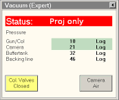
Remedy
Restart the vacuum system
Time requirement
5-10 minutes
Difficulty
Easy
Protocol
- Right of the column, below the screen are 4 buttons labelled ‘Do not touch’.
- Now, you will have to press the VAC button: press the button and release it again
- The status will change to “OFF” (you now have shut down the vacuum system)
- Repeat: press the VAC button again. The status will change to “STARTING”.
- Just wait. The starting sequence can be followed in the vacuum overview tab (bottom right) and takes about 5-6 minutes.
After this, you should be able to start the filament (“high tension / light”) and start working.
Optional: High tension is grayed out
- If you cannot start the high tension because the button is grayed out, it is because the safety mechanism also shut down the high tension to avoid arcs and shortcuts.
- The high tension button will be grayed out and the info reads: HT not enabled.
- The high tension can only be re-activated by a human, not by a computer.
- On the same panel, next to VAC, there is the button HT. Press it.
- Make sure you select 120 kV in the dropdown box next to the high tension button (default will be 20 kV).
- If the HT is still not available, press the HT button again. Do not press it a third time!
-
Align a misaligned objective aperture using low
Description
The objective aperture is crucial: it provides contrast, reduces artefacts and lowers aberration effects. A misaligned objective aperture is a bad thing.
When the aperture is not visible when you insert the aperture strip, it is dearly misaligned. This means: starting from a good image on the fluorescent screen, entering the aperture just gives darkness. If entering the aperture does not cause a (brief) darkness, then the strip is severely misaligned -> see below: severely misaligned aperture strip.
RemedySearch and center the hole of the aperture.
Time requirement
About 2-3 minutes
Difficulty
Medium
Protocol
Setup the imaging system
- Take the objective aperture out
- Magnification: at 1050X you should see the round green beam on the fluorescent screen.
- Now, setup the system as follows:
PARAMETER STATUS Sample holder Better with no sample, but it works when a normal TEM grid is inserted. Veleta Camera out (Green IN button on the remote) Beam On Column Valves Open (Status: Ready in vacuum tab) Objective aperture Out Magnification 170 X (LM 170X) C2 (intensity) 100% C1 (spot size) 1 Now you should see a round beam.
Find the beam
- Make sure the pin on the inner large knob of the aperture mechanism is pointed to ‘2’
- The beam should fill more or less the entire field of view.
- Insert the aperture strip.
- You should see a single small opening somewhere on the fluorescent screen (if everything is dark, see below: severely misaligned aperture strip)
- Use the knobs on the side and the on the front (the small one) of the aperture mechanism to align the hole to the center of the screen, around the 4 mm ring.
- Repeat aperture alignment (in the howtos, above) with a sample and in diffraction mode.
-
Align a severely misaligned objective aperture
Description
The objective aperture is crucial: it provides contrast, reduces artefacts and lowers aberration effects. A misaligned objective aperture is a bad thing. In some cases, the aperture (which sits on a strip) is completely removed from the beam. This situation can be recognized as follows: when switching objective aperture in (with the handle below the mechanism), you should always see a darkness for a very short time (this is the edge of the strip). If this is not the case, you are not looking through the aperture but besides the entire aperture strip.
Alternatively, your field of view is entirely dark when you enter the aperture (this is the case when the aperture strip completely blocks the beam).
Both cases can have severe consequences for the quality of your image and must be corrected.
Remedy
Realign the aperture strip. The entire alignment is done on the fluorescent screen, not in the software.
Time requirement
About 10 minutes
Difficulty
Medium
Protocol
Setup the imaging system
- Take the objective aperture out
- Magnification: at 1050X you should see the round green beam on the fluorescent screen. If not, setup the system as follows:
PARAMETER STATUS Sample holder Removed or no sample Veleta Camera out (Green IN button on the remote) Beam On Column Valves Open (Status: Ready in vacuum tab) Objective aperture Out Magnification 170 X (LM 170X) C2 (intensity) 100% C1 (spot size) 1 - Now you should see a round beam.
- If the image is still dark: see “I still see no beam”.
- If the beam is not round but kind of slit-like: see “the cryobox is misaligned”.
Optional: I still see no beam
- Locate the Y axis knob of the objective aperture mechanism: this is the knob sticking out to the right when standing in front of the TEM. It is located above the “out” sign.
- Turn it clockwise until you cannot turn is any further. You should now see a beam, with the objective aperture inserted (pointing to “in”).
Optional: the cryobox is misalgined
- If your beam is now convoluted with a curved, focused edge: you should align the cryobox
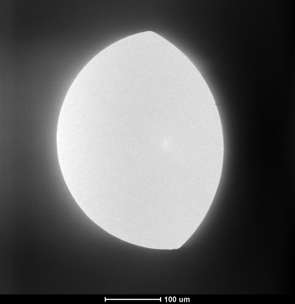
Cryo box (rounded edge) partially blocking the beam - Note: if the edge is not round but straight (see image below), then you are looking at the edge of the aperture strip. Skip these steps and go to “Find the aperture holes”.
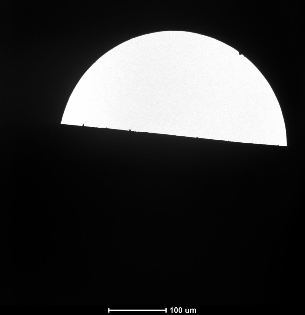
Aperture strip (straight edge) partially blocking the beam - To the left of the objective aperture (vis a vis the sample holder) is another aperture-like mechanism. It has the same buttons for mechanical alignment like the apertures. This is the cryobox. The cryobox is only visible at low magnifications and it is usually not necessary to align it.
- Use the X and Y knobs (not the inner large knob) to center the cryobox. You should now have the beam round and centered, with a diameter of 8-10 cm
Find the aperture holes
- Set the magnification to 490X. On the objective aperture mechanism, flip the switch to insert the aperture. If nothing happens or everything turns black, it is a sign that the aperture strip is misaligned.).
- With the large, inner on-axis knob (the one with the double function) set the position to 1.
- Turn the Y axis knob (the large on-axis knob, now using the outside part) all the way in one direction. Then turn is all the way in the other direction. Finally, try to position it somewhere halfway these extreme positions. It does not have to be super-precise.
- Turn the X axis knob (the single knob above the “out” sign, not the double knob system in the middle of the mechanism) counterclockwise (or clockwise if you just see darkness). After some turns (maximum 4) you should see a dark object moving in from below. This is the aperture strip. Next step: finding the holes in the aperture strip.
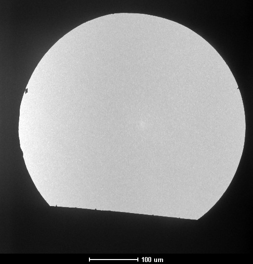
Aperture strip entering the field of view (from the bottom) - With the edge of the aperture strip going though the middle of your screen, turn the X axis knob counterclockwise for about 3-4 full turns. CAUTION: do not turn is further than 6 full turns (the knob may fall off, you will feel the reduced resistance while turning the knob).
- Somewhere between turn 3 and 4 the aperture will appear. Use X and Y knobs to center it on the fluorescent screen.
Aperture 1 appearing after about 3 full turns - Switch the mechanism to aperture position 2 (the standard position) and center it on the fluorescent screen with the X and Y buttons (should not be too misaligned).
- Magnify to 6000 X. Fine adjustment using the standard alignment procedure (in diffraction mode and with a sample) will still be needed (see your booklet)
Log book entry
Inform the admin about the severely misaligned aperture and make an entry in the log book that the microscope PC was restarted.
-
Strange holder / dust stopper inserted
If you see this situation:
– the holder is not in the goniometer, but in the holder stand on the desk
– instead a weird looking plug with one side seemingly cut off tangentially is in the goniometer
This is ok. The weird object is a dust stopper and is sometimes used by the technicians. You can just pull it out (in the same way you pull out the holder in the last step of the holder retraction). No need to turn it clockwise, just pull.
Brand
Tecnai Spirit | acquired 2014
Features
BioTwin lens | 120 kV LaB6 emitter | 3Å resolution limit
Detectors
Veleta 2048×2048 wide angle | Eagle 4096×4096 bottom mount
Technical
Computized stage | Gatan cryoholder | Single tilt tomography
Condenser apertures 200 μm | 100 μm | 50 μm | 30 μm
Objective apertures 100 μm | 40 μm | 20 μm | 10 μm